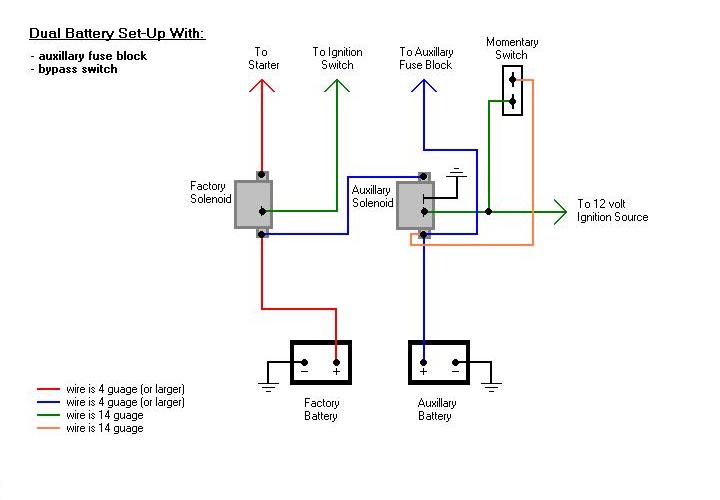
When it comes to understanding the intricacies of electrical systems in vehicles, having a clear grasp of a 12v Continuous Duty Solenoid Wiring Diagram is crucial. These diagrams provide a visual representation of how the various components in a circuit are connected, making it easier for mechanics to troubleshoot issues and ensure that the electrical system functions properly.
Why are 12v Continuous Duty Solenoid Wiring Diagrams Essential?
1. They help identify the connections between different components in the electrical system.
2. They provide a roadmap for installing new components or making repairs.
3. They assist in diagnosing electrical problems quickly and accurately.
How to Read and Interpret 12v Continuous Duty Solenoid Wiring Diagrams
- Study the key or legend provided with the diagram to understand the symbols and colors used.
- Follow the flow of the diagram from the power source to the load to trace the circuit path.
- Pay attention to the connections between components and the direction of current flow.
Using 12v Continuous Duty Solenoid Wiring Diagrams for Troubleshooting
By referring to the wiring diagram, mechanics can:
- Identify the root cause of electrical problems such as shorts or open circuits.
- Check for continuity between components to pinpoint faulty connections or components.
- Verify proper grounding and wiring connections to ensure the system operates efficiently.
It is important to exercise caution when working with electrical systems and using wiring diagrams. Here are some safety tips and best practices:
- Always disconnect the battery before working on any electrical components.
- Use insulated tools to prevent electrical shocks.
- Double-check all connections and wiring before re-energizing the system.
- Refer to the vehicle’s service manual for specific instructions and safety precautions.
12v Continuous Duty Solenoid Wiring Diagram
12 Volt Continuous Duty Solenoid Wiring Diagram – Wiring Diagram and
[DIAGRAM] Acdelco 12 Volt Solenoid Wiring Diagram – MYDIAGRAM.ONLINE
![12v Continuous Duty Solenoid Wiring Diagram [DIAGRAM] Acdelco 12 Volt Solenoid Wiring Diagram - MYDIAGRAM.ONLINE](http://txinel.com/images/24200_drawing_lg.gif)
Cole Hersee Continuous Duty Solenoid Wiring Diagram – Herbally

Continuous Duty Solenoid Wiring Diagram – Artled

Zoya Circuit: Cole Hersee 24059 Solenoid Wiring Diagram

12 Volt Continuous Solenoid Wiring – Wiring Flow Schema
