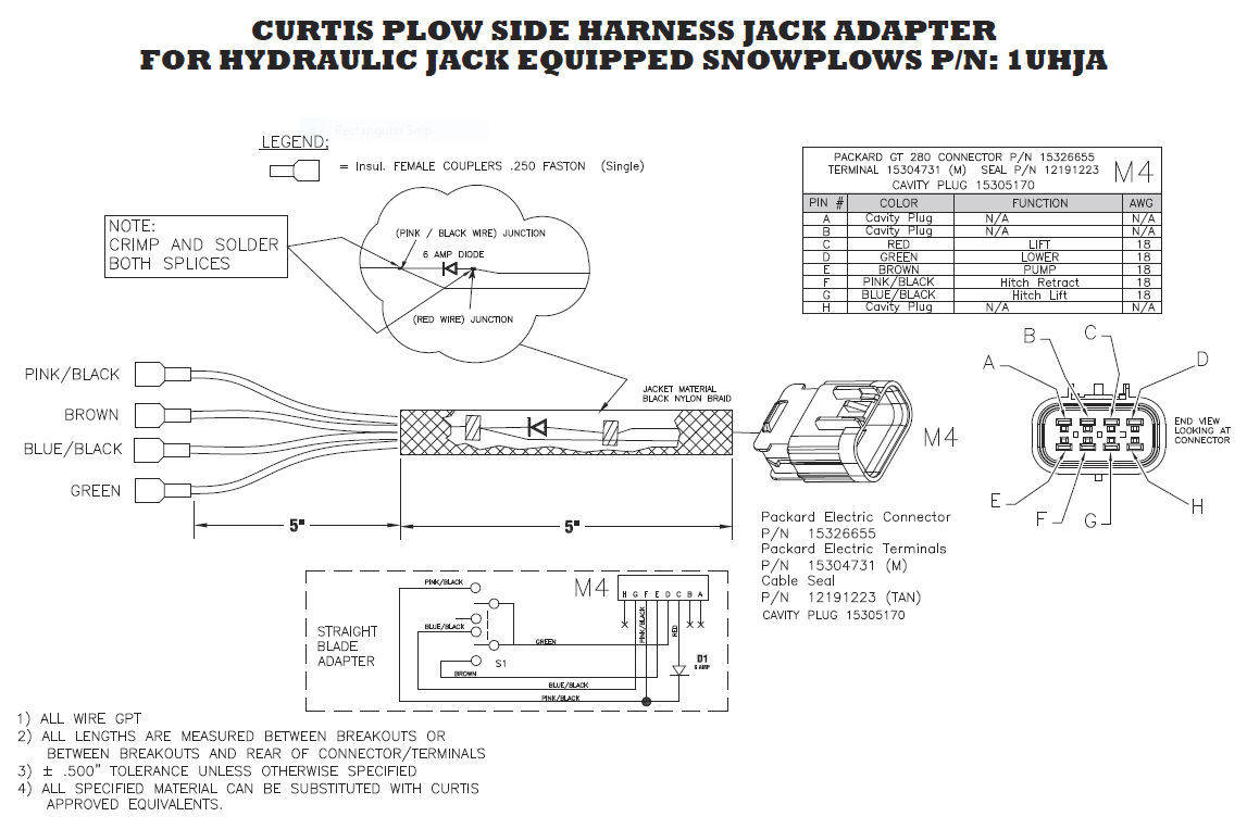
When it comes to ensuring the proper functioning of your Curtis plow, understanding the Curtis Plow Wiring Diagram is crucial. These diagrams provide a visual representation of the electrical system in your plow, allowing you to troubleshoot issues and make repairs effectively.
Why Curtis Plow Wiring Diagrams are Essential
Curtis Plow Wiring Diagrams are essential for several reasons:
- They help you understand how the different components of the electrical system are connected.
- They provide a roadmap for diagnosing and fixing electrical issues.
- They ensure that you make the correct connections when installing new components or making repairs.
How to Read and Interpret Curtis Plow Wiring Diagrams
Reading and interpreting Curtis Plow Wiring Diagrams may seem daunting at first, but with some guidance, it becomes much easier:
- Start by familiarizing yourself with the symbols and abbreviations used in the diagram.
- Follow the lines and connections to understand how the different components are linked together.
- Paying attention to colors and labels can help you identify specific wires and components.
Using Curtis Plow Wiring Diagrams for Troubleshooting
Curtis Plow Wiring Diagrams are invaluable tools when it comes to troubleshooting electrical problems:
- Identify the specific circuit that is causing the issue by tracing the wiring in the diagram.
- Check for continuity and voltage at various points in the circuit to pinpoint the problem area.
- Refer to the diagram to determine the correct sequence of components and connections.
Importance of Safety
Working with electrical systems can be dangerous, so it’s important to prioritize safety:
- Always wear appropriate protective gear, such as gloves and safety glasses.
- Disconnect the power source before working on the electrical system.
- Double-check your connections before turning the power back on to prevent short circuits.
Curtis Plow Wiring Diagram
Curtis Snow Plow 3000 Wiring Diagram

Curtis Snow Plow 3000 Wiring Diagram

Curtis Snow Plow Wiring Diagram For Your Needs

Curtis Snow Plow 3000 Wiring Diagram – Lace Art

Curtis Plow Wiring Diagram On Direction

Wiring Diagram For A Curtis Snow Plow
