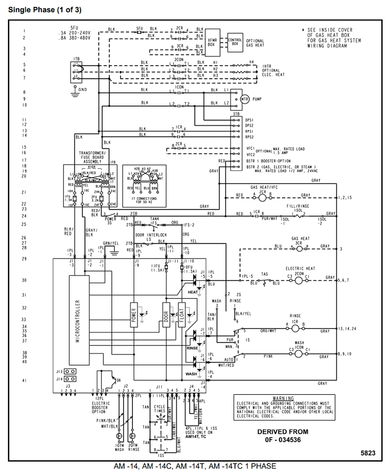
Electrical Wiring Yamaha 703 Remote Control Wiring Diagram is a vital tool for understanding the electrical connections and components of the Yamaha 703 remote control system. By referring to this diagram, mechanics and enthusiasts can troubleshoot electrical issues, make modifications, or install new components with confidence.
Importance of Electrical Wiring Yamaha 703 Remote Control Wiring Diagram
Understanding the Yamaha 703 remote control wiring diagram is crucial for several reasons:
- Ensures proper installation of new components
- Facilitates troubleshooting of electrical issues
- Helps in identifying faulty connections or components
- Avoids electrical hazards and damage to the system
Reading and Interpreting Electrical Wiring Yamaha 703 Remote Control Wiring Diagram
Reading and interpreting the Yamaha 703 remote control wiring diagram may seem daunting at first, but with some guidance, it becomes much more manageable:
- Understand the symbols and abbreviations used in the diagram
- Follow the flow of electrical current through the system
- Identify the different components and their connections
- Refer to the color codes for wires to ensure proper connections
Using Wiring Diagrams for Troubleshooting
When faced with electrical problems in the Yamaha 703 remote control system, the wiring diagram can be a lifesaver:
- Trace the electrical path to pinpoint the issue
- Check for continuity and voltage at key points in the system
- Compare the actual wiring with the diagram to identify discrepancies
- Consult the diagram to find the location of specific components for inspection or replacement
Importance of Safety
When working with electrical systems and using wiring diagrams, safety should always be the top priority:
- Turn off power sources before working on the system
- Use insulated tools to prevent electrical shocks
- Avoid working on wet or damp surfaces
- Double-check connections before restoring power to the system
Electrical Wiring Yamaha 703 Remote Control Wiring Diagram
Yamaha 703 Remote Control Wiring Diagram

Electrical Wiring Yamaha 703 Remote Control Wiring Diagram

Yamaha 703 Control Box Wiring Diagram Chart Printable – Shane Wired

electrical wiring yamaha 703 remote control wiring diagram
The Ultimate Guide to Understanding Yamaha 703 Remote Control Wiring

Yamaha 703 Remote Control Box Wiring Diagram – Circuit Diagram
