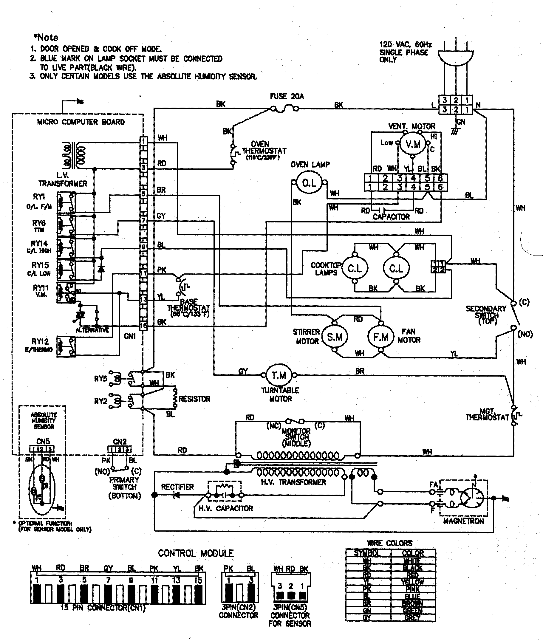
Ge Oven Wiring Diagram
Ge Oven Wiring Diagrams are crucial tools for understanding the electrical systems of GE ovens. These diagrams provide a visual representation of the wiring layout and connections within the oven, helping technicians troubleshoot issues and make repairs efficiently.
Why Ge Oven Wiring Diagrams are essential
- Helps identify components and their corresponding connections
- Aids in diagnosing electrical problems
- Assists in proper installation and maintenance
- Ensures safe handling of electrical systems
How to read and interpret Ge Oven Wiring Diagrams effectively
When reading Ge Oven Wiring Diagrams, it’s essential to understand the symbols and color codes used in the diagram. Here are some tips to help you interpret the diagrams:
- Refer to the legend or key provided in the diagram for symbol meanings
- Follow the wiring paths to trace connections between components
- Pay attention to color codes for wires to identify specific circuits
- Use a multimeter to verify continuity and voltage levels
Using Ge Oven Wiring Diagrams for troubleshooting electrical problems
Ge Oven Wiring Diagrams can be invaluable when troubleshooting electrical issues in ovens. By following the wiring diagram, technicians can:
- Identify faulty components or wiring connections
- Locate short circuits or open circuits within the system
- Verify proper voltage levels at different points in the circuit
- Ensure correct installation of new components or wiring repairs
Safety is paramount when working with electrical systems, including Ge Oven Wiring Diagrams. Here are some important safety tips to keep in mind:
- Always disconnect power to the oven before working on the electrical system
- Wear appropriate personal protective equipment, such as insulated gloves and goggles
- Avoid working on live circuits to prevent electric shocks or injuries
- Familiarize yourself with the specific wiring diagram and follow proper procedures
Ge Oven Wiring Diagram
GE Oven Schematic and Wiring Diagram – YouTube

Ge Electric Oven Wiring Diagram

Ge Microwave Wiring Diagram : Schematic and Wiring Diagram for the GE

The Ultimate GE Wall Oven Wiring Diagram Guide: Simplify Your DIY Project!

⭐ Ge Electric Cooktop Wiring Diagram ⭐

Jbp24 Ge Oven Wiring Schematic
