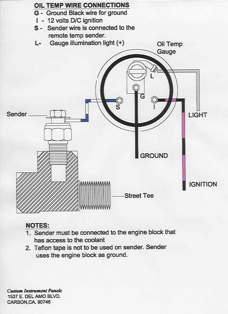
When working on a vehicle’s electrical system, understanding the heat gauge wiring diagram is crucial. This diagram provides a visual representation of how the heat gauge is connected to the vehicle’s electrical system, helping mechanics troubleshoot and diagnose issues effectively.
Importance of Heat Gauge Wiring Diagrams
- Helps identify the components of the heat gauge system
- Assists in locating the wiring connections for troubleshooting
- Ensures proper installation and maintenance of the heat gauge
Reading and Interpreting Heat Gauge Wiring Diagrams
Reading a heat gauge wiring diagram can seem daunting at first, but with a bit of practice, it becomes a valuable tool for mechanics. Here’s how to effectively interpret the diagram:
- Identify the different components of the heat gauge system
- Follow the lines to understand the wiring connections
- Pay attention to symbols and color codes for accurate interpretation
Using Heat Gauge Wiring Diagrams for Troubleshooting
When faced with electrical problems related to the heat gauge, the wiring diagram can be a lifesaver. Here’s how to use it for troubleshooting:
- Trace the wiring connections to identify any loose or damaged wires
- Check for continuity using a multimeter to pinpoint the issue
- Refer to the diagram to understand the circuit and locate potential faults
Safety Tips for Working with Heat Gauge Wiring Diagrams
Working with electrical systems can be dangerous, so it’s essential to prioritize safety at all times. Here are some tips to keep in mind:
- Always disconnect the vehicle’s battery before working on the electrical system
- Use insulated tools to prevent electric shocks
- Avoid working on the wiring when the engine is running
- Refer to the vehicle’s manual for specific safety precautions related to electrical work
Heat Gauge Wiring Diagram
Electric Temperature Gauge Wiring Diagram – Easy Wiring

Hvac Training on Electric Heaters – HVAC Training for Beginners

Installing oil temperature gauge out of Ram SRT10 | Dodge SRT Forum

Ruud Heat Pump Wiring Diagram – Wiring Diagrams – Heat Pump Wiring

Temperature Gauge Wiring Diagram For Your Needs

Temp Gauge Wiring Diagram
