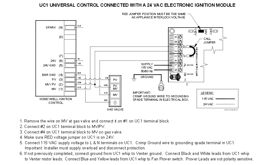
Inducer Motor Wiring Diagrams are essential tools for understanding and troubleshooting the electrical systems of HVAC systems. These diagrams provide a visual representation of the wiring connections and components involved in the operation of the inducer motor, which plays a crucial role in the proper functioning of the heating and cooling systems.
Importance of Inducer Motor Wiring Diagrams
- Help in understanding the electrical connections of the inducer motor
- Aid in identifying faulty wiring or components
- Provide guidance for proper installation and maintenance
- Assist in troubleshooting electrical issues
Reading and Interpreting Inducer Motor Wiring Diagrams
When looking at an inducer motor wiring diagram, it’s important to understand the symbols and connections used. Here are some tips for effectively reading and interpreting these diagrams:
- Identify the components: Understand the symbols used to represent different parts of the inducer motor.
- Follow the wiring: Trace the wiring connections from the power source to the motor to ensure proper connectivity.
- Check for labels: Pay attention to any labels or markings on the diagram that provide additional information.
Using Inducer Motor Wiring Diagrams for Troubleshooting
Inducer motor wiring diagrams are invaluable tools for troubleshooting electrical problems in HVAC systems. By following the wiring connections and understanding the components involved, you can pinpoint issues and make necessary repairs. Here’s how inducer motor wiring diagrams can help in troubleshooting:
- Identifying faulty wiring: By comparing the actual wiring to the diagram, you can identify any discrepancies that may be causing issues.
- Testing components: Use the diagram to locate and test individual components to determine if they are functioning properly.
- Following troubleshooting steps: Many wiring diagrams include troubleshooting steps that can guide you through the process of diagnosing and fixing problems.
Safety First
When working with electrical systems and using wiring diagrams, it’s crucial to prioritize safety. Here are some important safety tips and best practices to keep in mind:
- Always turn off the power: Before working on any electrical system, make sure to turn off the power source to prevent the risk of electrical shock.
- Use appropriate tools: Use insulated tools and equipment designed for electrical work to avoid accidents.
- Double-check connections: Verify all connections before turning the power back on to ensure everything is properly secured.
Inducer Motor Wiring Diagram
Inducer Motor Diagram – Rock Wiring

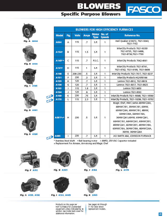
Inducer Fan Motor Wiring Diagram

What is Speed Control of Induction Motor? | Linquip

Induction Motor Working Principle – StudiousGuy

Rotary 3 Phase Converter Wiring Diagram – downdload

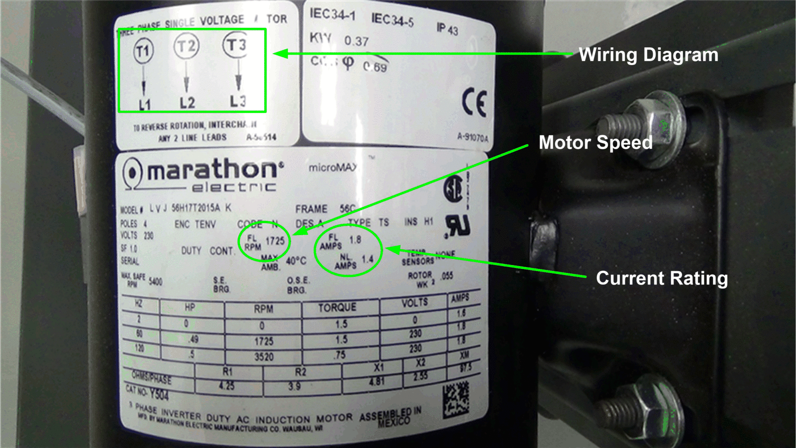
Induction Motor Wiring Diagram 1 Phase Induction Motor Wiring Diagram
