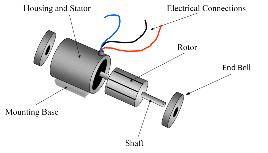
Induction Motor Wiring Diagram is a detailed schematic that illustrates the connections and components of an induction motor’s electrical system. It provides a visual representation of how the motor is wired and helps in understanding the various components involved in the motor operation.
Importance of Induction Motor Wiring Diagram
Understanding Induction Motor Wiring Diagram is crucial for several reasons:
- Ensures proper installation of the motor
- Aids in troubleshooting electrical issues
- Helps in identifying faulty components
- Facilitates maintenance and repairs
Reading and Interpreting Induction Motor Wiring Diagram
When reading an Induction Motor Wiring Diagram, it is important to:
- Identify the different components such as coils, capacitors, switches, etc.
- Understand the connections between the components
- Follow the flow of current through the system
- Refer to the legend or key for symbols used in the diagram
Using Induction Motor Wiring Diagram for Troubleshooting
Induction Motor Wiring Diagram can be a valuable tool for troubleshooting electrical problems. It helps in:
- Locating the source of the issue within the motor system
- Checking for continuity and proper connections
- Identifying faulty components that need replacement
- Verifying the correct wiring configuration
Safety Tips for Working with Induction Motor Wiring Diagram
When working with electrical systems and using wiring diagrams, it is essential to prioritize safety. Here are some safety tips and best practices:
- Always turn off power before working on the motor
- Use insulated tools to prevent electric shock
- Avoid working in wet or damp conditions
- Wear appropriate personal protective equipment (PPE)
- Follow proper lockout/tagout procedures to prevent accidental startup
Induction Motor Wiring Diagram
WIRING DIAGRAM STAR-DELTA CONNECTION IN 3-PHASE INDUCTION MOTOR

Types of Single Phase Induction Motors | Single Phase Induction Motor

Electronic – How to wire up single phase induction motor – Valuable

Clarke Single Phase Induction Motor Wiring Diagram

Operation of Induction Motor – Engineering Learn

Types of Single Phase Induction Motors | Single Phase Induction Motor
