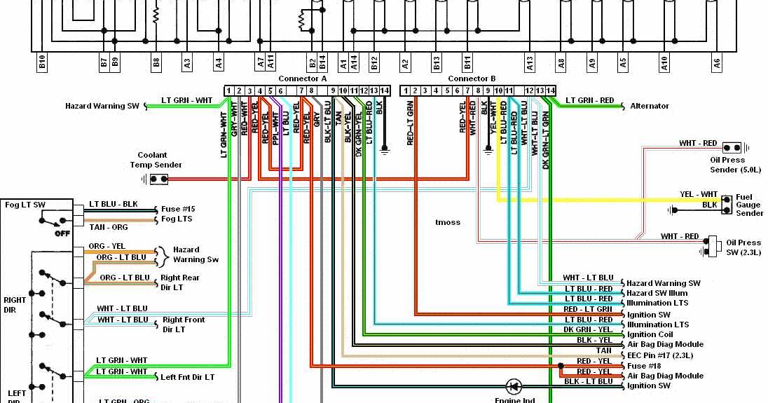
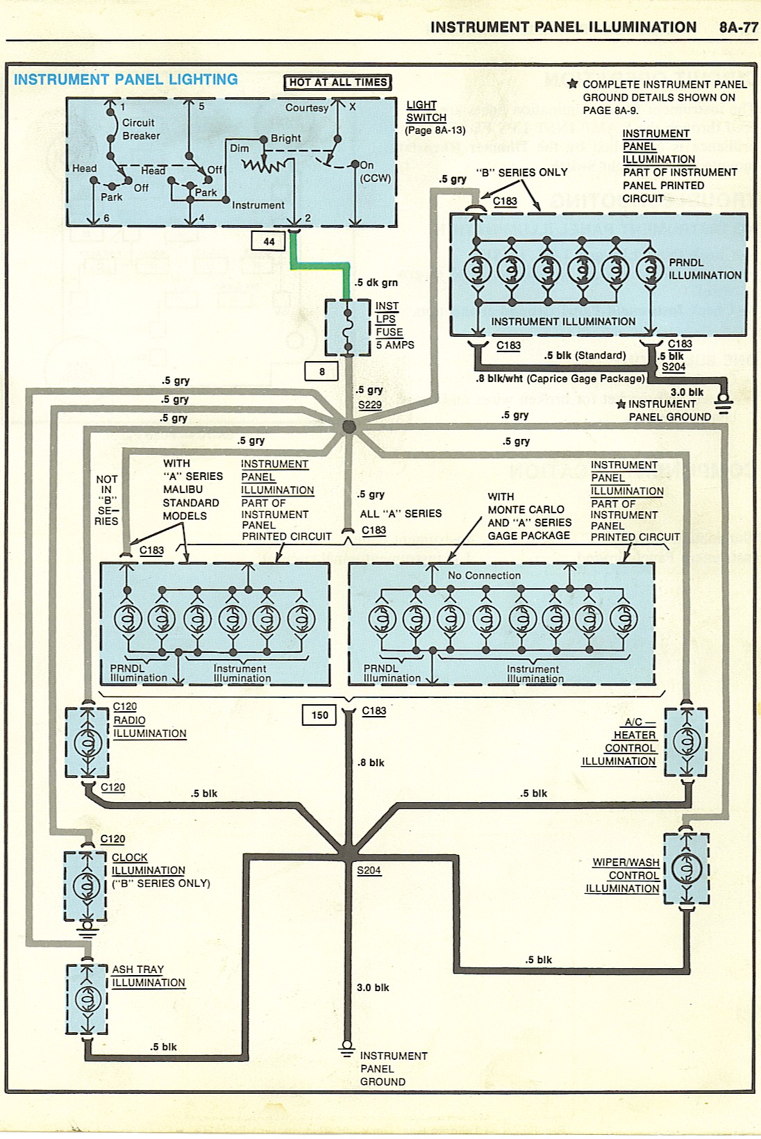
When working on vehicles, understanding the instrument cluster wiring diagram is crucial for any mechanic. This diagram is a visual representation of the electrical connections within the instrument cluster, showing how each component is connected and powered. By studying this diagram, mechanics can troubleshoot electrical issues, identify faulty connections, and ensure proper functioning of the instrument cluster.
Why are Instrument Cluster Wiring Diagrams Essential?
- Provide a detailed overview of the electrical system within the instrument cluster
- Help identify the location of each component and its wiring connections
- Assist in troubleshooting electrical problems efficiently
- Ensure proper installation and repair of the instrument cluster
How to Read and Interpret Instrument Cluster Wiring Diagrams Effectively
Reading and interpreting instrument cluster wiring diagrams may seem daunting at first, but with the right approach, it can be a valuable tool for any mechanic. Here are some tips to help you understand these diagrams:
- Start by familiarizing yourself with the symbols and color codes used in the diagram
- Follow the flow of electricity from the power source to each component
- Identify the connections between components and understand how they interact
- Refer to the key or legend provided to decode any abbreviations or acronyms used
Using Instrument Cluster Wiring Diagrams for Troubleshooting Electrical Problems
Instrument cluster wiring diagrams are invaluable tools for diagnosing and resolving electrical issues in vehicles. By following the wiring diagram, mechanics can pinpoint the source of the problem, whether it’s a faulty connection, broken wire, or malfunctioning component. Here are some steps to effectively use these diagrams for troubleshooting:
- Identify the specific area of the instrument cluster that is experiencing issues
- Trace the wiring connections related to the problematic component
- Check for continuity, voltage, and resistance at various points in the circuit
- Compare the actual readings with the expected values to determine the root cause of the problem
Safety Tips for Working with Instrument Cluster Wiring Diagrams
When dealing with electrical systems and using wiring diagrams, safety should always be a top priority. Here are some safety tips and best practices to keep in mind:
- Always disconnect the battery before working on any electrical components
- Use insulated tools to prevent electric shocks
- Avoid working on wet surfaces or in damp conditions
- Double-check your connections and wiring before reassembling the instrument cluster
Instrument Cluster Wiring Diagram
Instrument Cluster Wiring Diagrams Of 1987 Ford Mustang 3rd Generation

Instrument Cluster Wiring Diagram

Gm Instrument Cluster Wiring Diagram

1986 C10 Instrument Cluster Wiring Diagram

2005 Chevy Silverado Instrument Cluster Wiring Diagram

Bmw E36 Instrument Cluster Wiring Diagram
