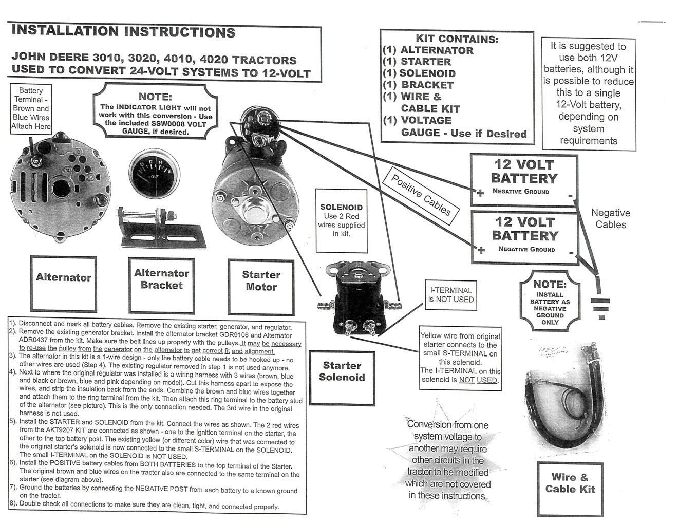
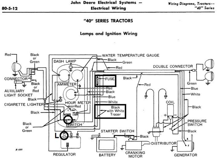
John Deere 3020 Wiring Diagrams are an essential tool for anyone working on the electrical system of this iconic tractor model. These diagrams provide a visual representation of the electrical connections and components within the tractor, helping users troubleshoot issues, make repairs, or perform upgrades.
Why are John Deere 3020 Wiring Diagrams essential?
- Help in understanding the electrical system of the tractor
- Aid in diagnosing and fixing electrical problems
- Assist in installing new equipment or components
- Ensure proper wiring connections and prevent electrical mishaps
How to read and interpret John Deere 3020 Wiring Diagrams effectively
To effectively read and interpret a John Deere 3020 Wiring Diagram, it is important to understand the symbols and color codes used in the diagram. Each wire and component is represented by a specific symbol or color, which helps in identifying them accurately. It is also crucial to follow the wiring diagram step by step, starting from the power source and tracing the connections to the intended component.
Using John Deere 3020 Wiring Diagrams for troubleshooting electrical problems
- Identify the affected circuit on the wiring diagram
- Check for continuity and voltage at various points along the circuit
- Compare the actual wiring with the diagram to pinpoint any discrepancies or faults
- Refer to the wiring diagram to locate and test specific components
Importance of safety when working with electrical systems and using wiring diagrams
When working with electrical systems and using wiring diagrams, safety should always be a top priority. Here are some safety tips and best practices to follow:
- Always disconnect the power source before working on the electrical system
- Use insulated tools to prevent electric shock
- Avoid working on electrical systems in wet or damp conditions
- Double-check all connections and wiring before reapplying power
- If in doubt, consult a professional or seek expert advice
John Deere 3020 Wiring Diagram
John Deere 3020 Wiring Diagram

John Deere 3020 Wiring Diagram Pdf For Your Needs

John Deere 3020 Wiring Diagram – Wiring Diagram Pictures

Q&A: John Deere 3020 Starter Wiring Diagram & More | JustAnswer

John Deere 3020 Wiring Diagram Pdf | autocardesign

John Deere 3020 Diesel Wire Diagram Rar leelwelby
