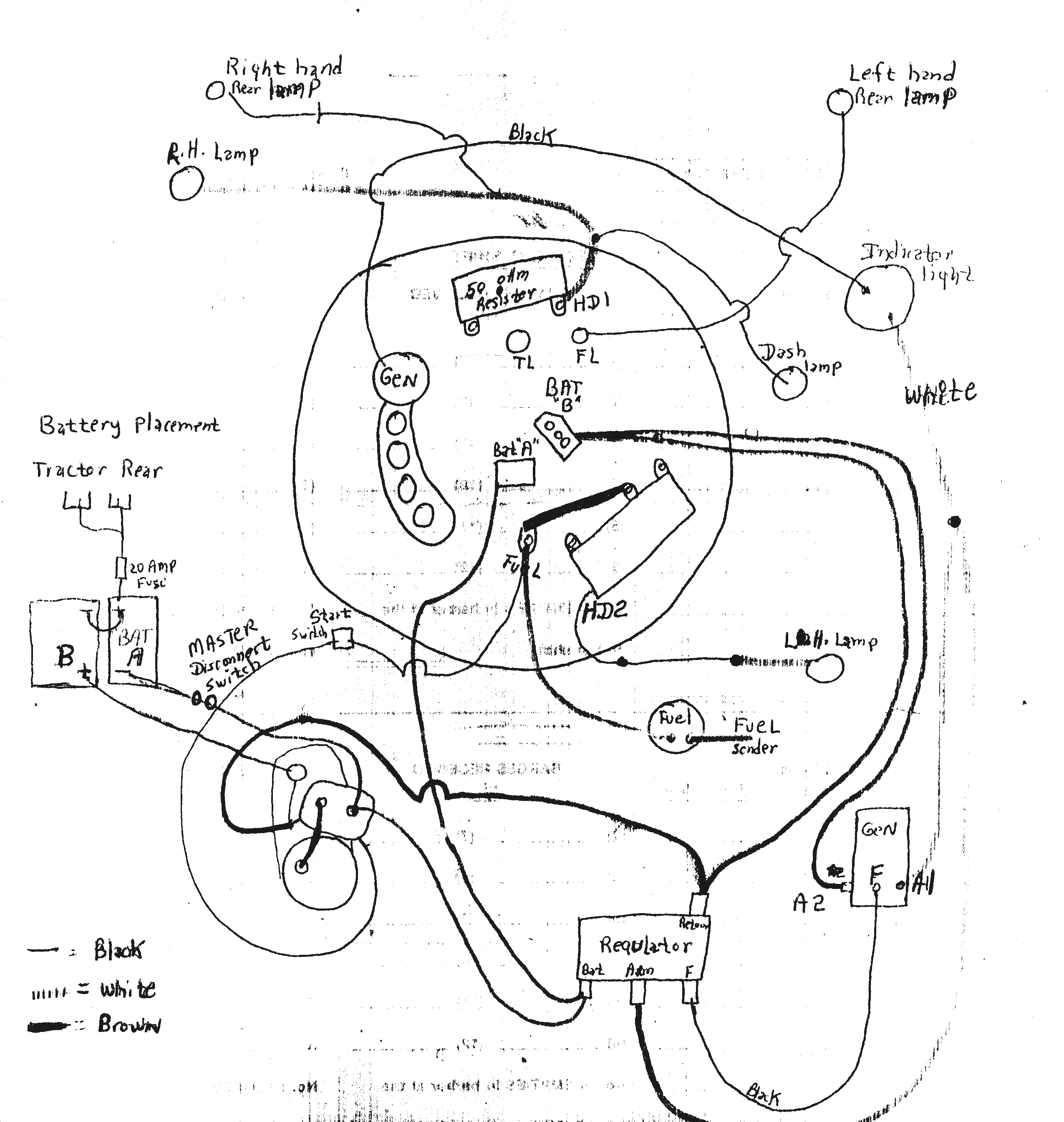
John Deere 4020 24 Volt Wiring Diagram is a crucial resource for mechanics and technicians working on this particular model of tractor. It provides a detailed illustration of the electrical system, allowing users to understand the wiring connections and troubleshoot any issues effectively.
Why are John Deere 4020 24 Volt Wiring Diagrams essential?
- Ensure proper wiring connections
- Identify electrical components and their functions
- Troubleshoot electrical issues accurately
- Prevent damage to the electrical system
How to read and interpret John Deere 4020 24 Volt Wiring Diagram effectively
- Understand the symbols and colors used in the diagram
- Follow the wiring paths from one component to another
- Refer to the legend or key for clarification on symbols
- Use a magnifying glass for small details
Using John Deere 4020 24 Volt Wiring Diagram for troubleshooting electrical problems
- Identify the specific area of the electrical system causing the issue
- Trace the wiring connections related to the problem component
- Check for continuity, voltage, and resistance using a multimeter
- Refer to the wiring diagram to locate potential faulty connections or components
Safety tips when working with electrical systems and wiring diagrams
- Always disconnect the battery before working on the electrical system
- Use insulated tools to prevent electric shock
- Avoid working on the electrical system in wet or damp conditions
- Double-check all connections before turning on the power
John Deere 4020 24 Volt Wiring Diagram
Step-by-Step Guide: Understanding the John Deere 4020 24 Volt Wiring

John Deere 4020 Wiring Schematic

John Deere 4020 Wiring Schematic

26 John Deere 4020 24 Volt Wiring Diagram – Wiring Database 2020
️John Deere 4020 24v To 12v Conversion Wiring Diagram Free Download
