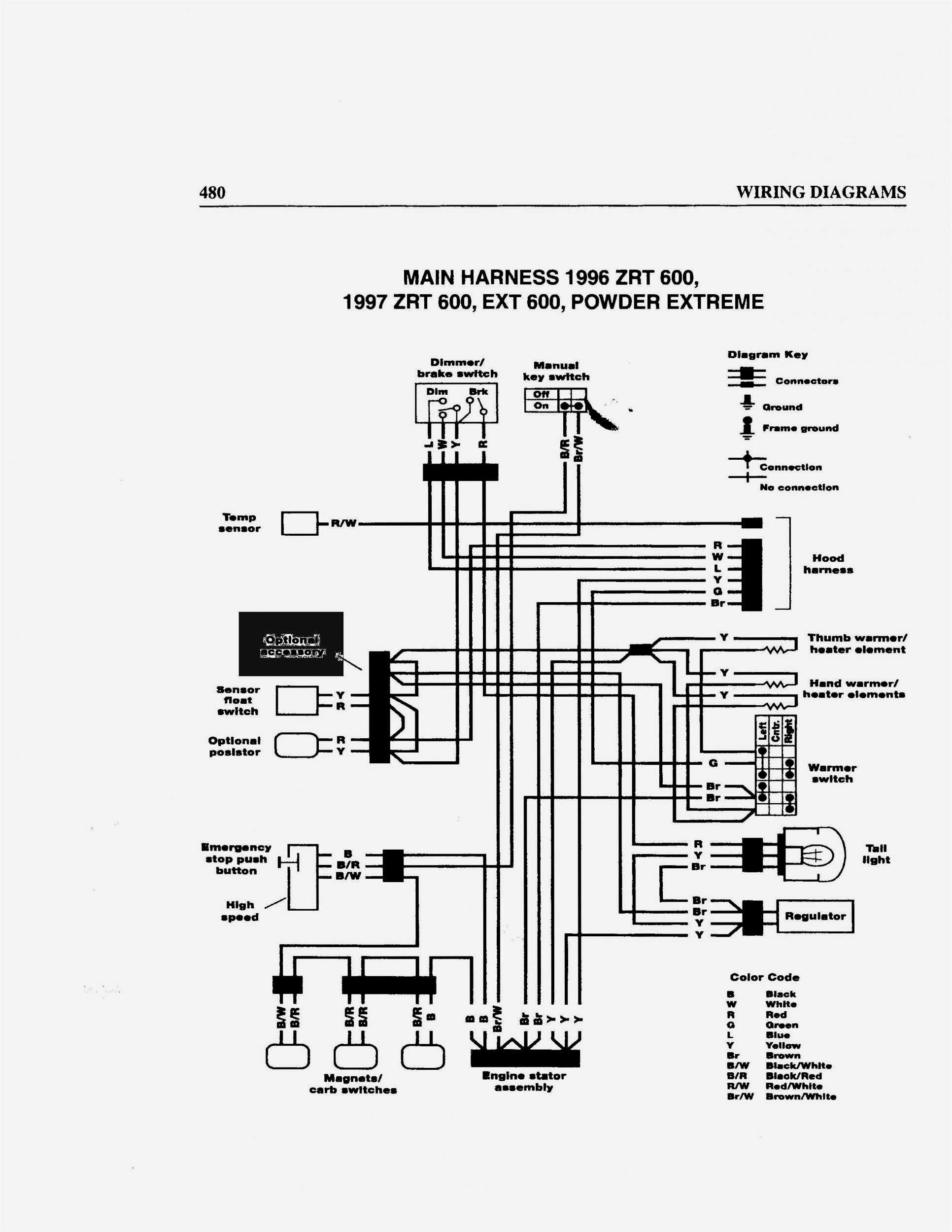
About John Deere La105 Wiring Diagram
John Deere La105 Wiring Diagram is a crucial tool for understanding the electrical system of the John Deere La105 lawn tractor. It provides a visual representation of the wiring and electrical components in the vehicle, helping mechanics and DIY enthusiasts troubleshoot and repair electrical issues efficiently.
Importance of John Deere La105 Wiring Diagram
- Helps in understanding the electrical system of the vehicle
- Aids in diagnosing and troubleshooting electrical problems
- Guides in proper installation and repair of electrical components
Reading and Interpreting John Deere La105 Wiring Diagram
When looking at a John Deere La105 Wiring Diagram, it is essential to understand the symbols and color codes used. Each wire is represented by a specific color, and symbols indicate different components such as switches, relays, and connectors. By following the wiring diagram, one can trace the path of electrical current and identify any faults or issues.
Using John Deere La105 Wiring Diagram for Troubleshooting
John Deere La105 Wiring Diagram can be a valuable tool for diagnosing electrical problems in the vehicle. By following the wiring diagram and checking for continuity, voltage, and resistance at various points, one can pinpoint the source of the issue and make necessary repairs. It saves time and effort by providing a clear roadmap for troubleshooting.
Importance of Safety
When working with electrical systems and using wiring diagrams, safety should always be a top priority. Here are some safety tips and best practices:
- Always disconnect the battery before working on the electrical system
- Use insulated tools to prevent electrical shocks
- Avoid working on the wiring when the engine is running
- Double-check all connections and ensure they are secure before powering up the system
John Deere La105 Wiring Diagram
John Deere La105 Wiring Diagram

John Deere La105 Wiring Schematic – Wiring Diagram

John Deere La105 Wiring Schematic – Wiring Diagram

John Deere La105 Wiring Diagram

John Deere La105 Parts Diagram – General Wiring Diagram

John Deere La105 Wiring Diagram
