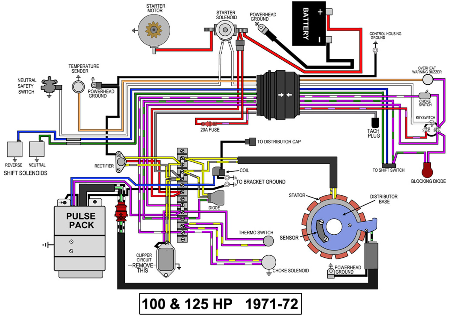
Johnson Ignition Switch Wiring Diagram
When it comes to the electrical system of your Johnson outboard motor, understanding the Johnson Ignition Switch Wiring Diagram is crucial. This diagram provides a visual representation of how the ignition switch is wired, helping you troubleshoot any electrical issues that may arise.
Why Johnson Ignition Switch Wiring Diagrams are Essential
- Ensure proper installation of the ignition switch
- Help diagnose electrical problems
- Prevent short circuits and other safety hazards
- Guide repairs and maintenance tasks
Reading and Interpreting Johnson Ignition Switch Wiring Diagrams
When looking at a Johnson Ignition Switch Wiring Diagram, it’s important to understand the symbols and colors used to represent different components. Additionally, pay attention to the direction of the wiring and the connections between each component.
Using Johnson Ignition Switch Wiring Diagrams for Troubleshooting
- Identify the source of electrical issues
- Check for continuity and voltage at various points
- Follow the wiring diagram step by step to pinpoint the problem
Importance of Safety
Working with electrical systems can be dangerous if proper precautions are not taken. Here are some safety tips to keep in mind:
- Always disconnect the battery before working on the electrical system
- Use insulated tools to prevent electric shock
- Avoid working in wet or damp conditions
- Double-check your work before re-connecting the battery
Johnson Ignition Switch Wiring Diagram
Johnson Outboard Ignition Switch Wiring Diagram – Collection – Wiring

Johnson Ignition Switch Wiring Diagram – Cadician's Blog

Johnson Outboard Ignition Wiring Diagram

Wiring Diagram For Johnson Outboard Ignition Switch – Wiring Digital

Johnson Outboard Ignition Switch Wiring Diagram – Collection
Johnson Ignition Switch Wiring Diagram – Database – Wiring Collection
