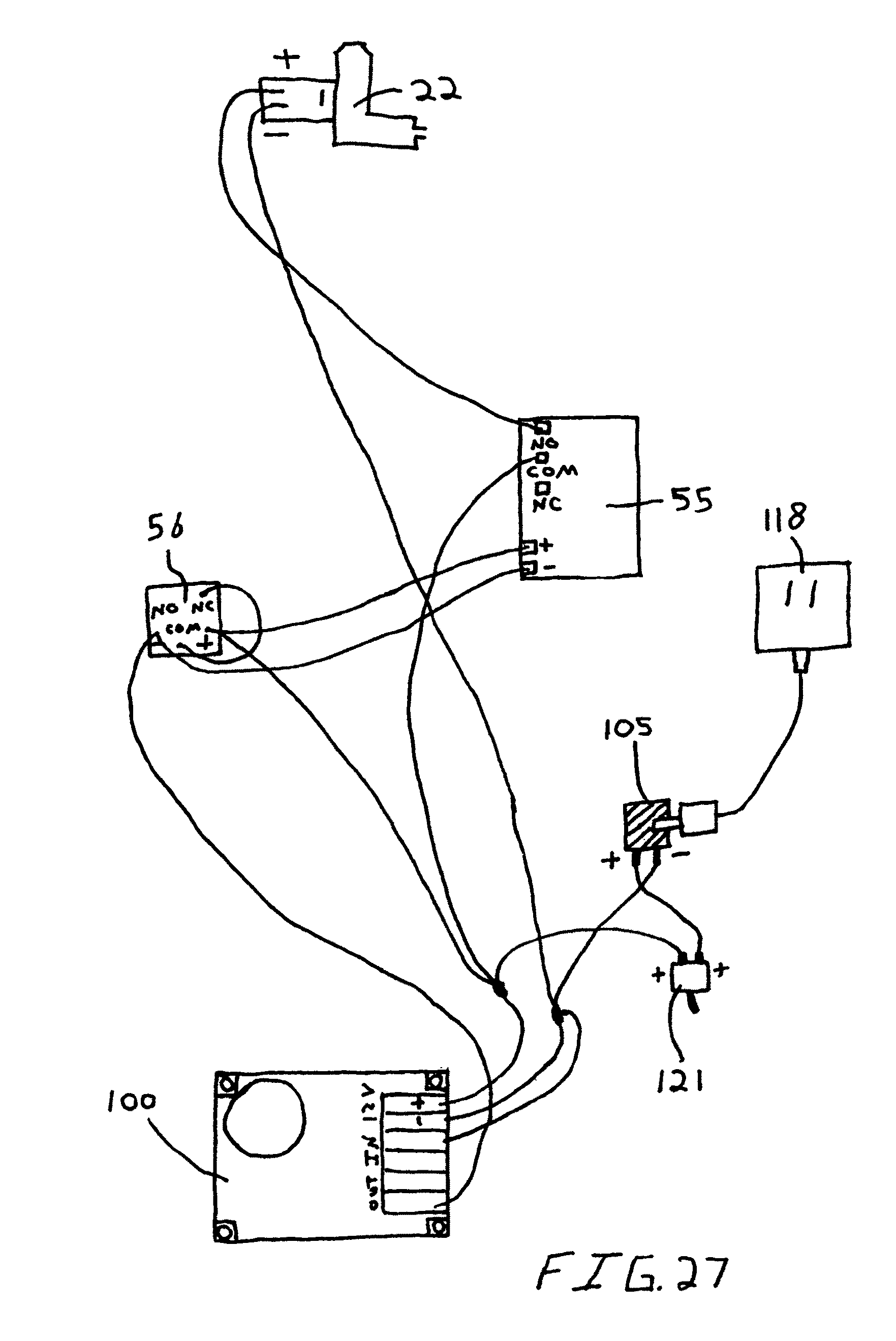
When it comes to electrical systems, having a clear understanding of L5 30 Plug Wiring Diagram is essential for proper installation and troubleshooting. These diagrams provide a visual representation of the wiring configuration for L5 30 plugs, helping users to connect the wires correctly and ensure safe operation of electrical devices.
Why L5 30 Plug Wiring Diagram are essential
- Ensure proper installation of L5 30 plugs
- Prevent electrical hazards and damage
- Aid in troubleshooting electrical issues
- Comply with electrical codes and standards
Reading and interpreting L5 30 Plug Wiring Diagram
When reading a L5 30 Plug Wiring Diagram, it is important to pay attention to the symbols and color codes used to represent different wires. The diagram typically shows the connections between the plug’s terminals and the corresponding wires, helping users to identify the correct wiring configuration for their specific application.
Using L5 30 Plug Wiring Diagram for troubleshooting
L5 30 Plug Wiring Diagram can be a valuable tool for troubleshooting electrical problems. By following the diagram and checking the connections, users can identify any issues with the wiring and make necessary repairs or adjustments. This can help to prevent electrical failures, malfunctions, and potential hazards.
Importance of safety
Working with electrical systems can be dangerous, so it is crucial to prioritize safety when using L5 30 Plug Wiring Diagram. Here are some safety tips and best practices to keep in mind:
- Always turn off the power before working on electrical systems
- Use insulated tools to avoid electric shock
- Double-check all connections before turning the power back on
- Wear appropriate personal protective equipment, such as gloves and goggles
- If you are unsure about any aspect of the wiring, seek professional help
L5 30 Plug Wiring Diagram
Nema L5 30r Wiring Diagram – inspireque

L5-30 Plug Wiring Diagram

NEMA L5-30 Power Flanged Inlet Receptacle 3P, 30 A, 125/250 V, Integra

Nema L15 30 Wiring Diagram
L5-30r Wiring Diagram

L5 30 Plug Wiring Diagram
