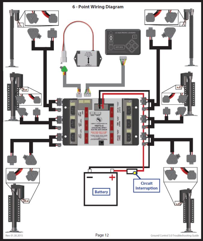
When it comes to ensuring the proper functioning of your RV’s stabilizer jacks, understanding the Lippert Stabilizer Jack Switch Wiring Diagram is crucial. This diagram provides a visual representation of the electrical connections within the system, allowing you to troubleshoot issues and make necessary repairs.
Why are Lippert Stabilizer Jack Switch Wiring Diagrams essential?
- Helps identify the various components of the stabilizer jack system
- Allows for troubleshooting of electrical issues
- Aids in understanding how the system operates
How to read and interpret Lippert Stabilizer Jack Switch Wiring Diagrams effectively
When examining a Lippert Stabilizer Jack Switch Wiring Diagram, it’s important to pay attention to the following:
- Color coding of wires
- Connection points for switches and motors
- Grounding points
Using Lippert Stabilizer Jack Switch Wiring Diagrams for troubleshooting electrical problems
By referencing the wiring diagram, you can pinpoint the source of electrical issues such as malfunctioning switches or motors. This allows you to make targeted repairs and get your stabilizer jacks back in working order.
Emphasizing safety when working with Lippert Stabilizer Jack Switch Wiring Diagrams
When dealing with electrical systems and wiring diagrams, it’s important to prioritize safety. Here are some key tips to keep in mind:
- Always disconnect power sources before working on electrical components
- Use insulated tools to prevent electrical shock
- Avoid working on wiring in wet or damp conditions
- Double-check all connections before restoring power to the system
Lippert Stabilizer Jack Switch Wiring Diagram
Lippert 298707 High Speed Power Stabilizer Jack

Lippert Stabilizer Jack Switch Wiring Diagram – Heavy Wiring

Lippert Stabilizer Jack Switch Wiring Diagram – Heavy Wiring

Lippert Electric Stabilizer Jacks Wiring Diagram, Wire Gauge

Wiring Diagram For Lipper Stabilizer Jacks | etrailer.com
