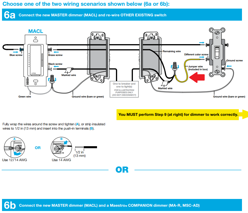
When it comes to installing and controlling fans in your home, understanding the Lutron Caseta Fan Control Wiring Diagram is crucial. This diagram provides a detailed overview of how the fan control system is wired and helps ensure that the installation process is done correctly and safely.
Why Lutron Caseta Fan Control Wiring Diagrams are Essential
- Helps ensure proper installation of the fan control system
- Provides a visual representation of how the components are connected
- Aids in troubleshooting electrical issues
- Ensures compliance with building codes and safety standards
Reading and Interpreting Lutron Caseta Fan Control Wiring Diagrams
When looking at a Lutron Caseta Fan Control Wiring Diagram, it’s important to understand the symbols and markings used. Each component will be labeled and connected with lines to indicate how they are wired together. Pay close attention to the key provided on the diagram to understand what each symbol represents.
Using Lutron Caseta Fan Control Wiring Diagrams for Troubleshooting
When faced with electrical problems related to your fan control system, the wiring diagram can be a valuable tool. By following the wiring diagram and checking the connections, you can identify any potential issues and make the necessary repairs or adjustments to get your system up and running smoothly.
Importance of Safety and Best Practices
Working with electrical systems can be dangerous, so it’s essential to prioritize safety at all times. When using Lutron Caseta Fan Control Wiring Diagrams, follow these safety tips:
- Always turn off the power before working on any electrical components
- Use insulated tools to prevent shock hazards
- Double-check all connections before restoring power to the system
- If you’re unsure about any aspect of the wiring, consult a professional electrician
Lutron Caseta Fan Control Wiring Diagram
Lutron Caséta Fan Control review: Smart control for your dumb ceiling

Lutron Maestro Fan Control And Light Dimmer Wiring

Lutron Caseta Fan Control – installation and setup – YouTube

Lutron Caseta Fan Switch Wiring Diagram Parts – Orla Wiring

Lutron Light Switch Wiring | Shelly Lighting

Lutron Caseta Wiring Diagram | tyello.com
