Introduction
A PID wiring diagram is a vital tool for any mechanic or technician working with electrical systems. It provides a detailed layout of the connections between various components, helping to ensure that the system functions correctly. Understanding how to read and interpret these diagrams is crucial for troubleshooting and maintaining electrical systems.
Why Pid Wiring Diagrams are Essential
PID wiring diagrams are essential for several reasons:
- They provide a visual representation of the electrical connections in a system.
- They help to identify the exact components and their locations within the system.
- They aid in troubleshooting by pinpointing potential issues with the electrical connections.
How to Read and Interpret Pid Wiring Diagrams Effectively
Reading and interpreting PID wiring diagrams effectively requires attention to detail and a systematic approach:
- Start by identifying the various components in the diagram.
- Understand the symbols and abbreviations used in the diagram.
- Follow the wiring paths from one component to another to understand the flow of electricity.
- Pay attention to the color-coding of wires to ensure correct connections.
Using Pid Wiring Diagrams for Troubleshooting Electrical Problems
PID wiring diagrams are invaluable for troubleshooting electrical problems:
- They help to isolate faulty components by tracing the wiring connections.
- They provide a roadmap for identifying and rectifying wiring errors or short circuits.
- They guide technicians in testing and measuring electrical signals to diagnose issues accurately.
Importance of Safety
Working with electrical systems and wiring diagrams requires strict adherence to safety protocols:
- Always turn off the power supply before working on any electrical system.
- Use insulated tools to prevent electric shock.
- Wear appropriate personal protective equipment, such as gloves and safety goggles.
- Double-check all connections before restoring power to the system.
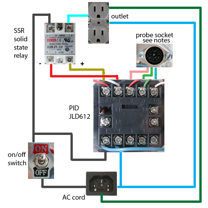
Pid Wiring Diagram
Pid Controller Wiring Diagram 230v

Pid Controller Wiring Diagram For Heat | touch sensor floor lamp besttt

Inkbird Pid Wiring Diagram – Zen Yarn

Pid Temperature Controller Wiring Diagram – Diagram Resource Gallery

How to Wire a PID Temp Controller with Pt100 Sensor | ATO.com

Electrical – Connecting PID Controller to SSR – Valuable Tech Notes
