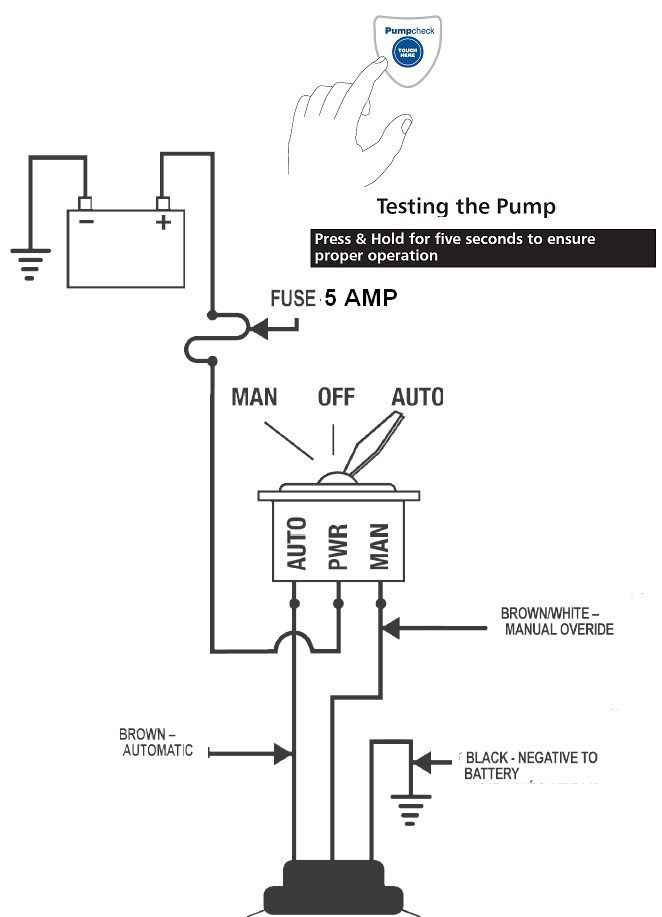
When it comes to marine electrical systems, understanding the Rule 500 Gph Automatic Bilge Pump Wiring Diagram is crucial for proper installation and troubleshooting. This diagram provides a visual representation of the electrical connections needed to ensure the bilge pump functions correctly.
Importance of Rule 500 Gph Automatic Bilge Pump Wiring Diagram
The Rule 500 Gph Automatic Bilge Pump Wiring Diagram is essential for the following reasons:
- Ensures proper installation of the bilge pump
- Helps identify and troubleshoot electrical issues
- Ensures safety by following correct wiring connections
Reading and Interpreting Rule 500 Gph Automatic Bilge Pump Wiring Diagram
When reading the wiring diagram, it’s important to understand the symbols and color codes used. Here are some tips for effectively interpreting the diagram:
- Identify the components: Understand what each symbol represents, such as the pump, switch, fuse, and power source.
- Follow the wires: Trace the paths of the wires to see how the components are connected.
- Pay attention to color codes: Different colors may indicate different functions or power sources.
Using Rule 500 Gph Automatic Bilge Pump Wiring Diagram for Troubleshooting
When facing electrical problems with the bilge pump, the wiring diagram can be a valuable tool for troubleshooting. Here’s how you can use it effectively:
- Check for loose connections: Inspect the diagram to ensure all connections are secure and properly aligned.
- Test the components: Use a multimeter to check for continuity and voltage at various points in the circuit.
- Compare with the actual wiring: Verify that the actual wiring matches the diagram to rule out any discrepancies.
Safety Tips for Working with Rule 500 Gph Automatic Bilge Pump Wiring Diagram
Working with electrical systems can be dangerous, so it’s important to prioritize safety. Here are some tips to keep in mind:
- Always disconnect power before working on the wiring.
- Use proper insulation and protection for exposed wires.
- Double-check connections to prevent short circuits or electrical shocks.
Rule 500 Gph Automatic Bilge Pump Wiring Diagram
Wiring An Automatic Bilge Pump

Rule 500 Gph Automatic Bilge Pump Wiring Diagram Collection
500 GPH Automatic Bilge Pumps, 24V

Rule Bilge Pump Wireing

Rule Mate RM500A Automatic Bilge Pump RM500 500 GPH

RULE INDUSTRIES 500 GPH Electric Bilge Pump | West Marine
