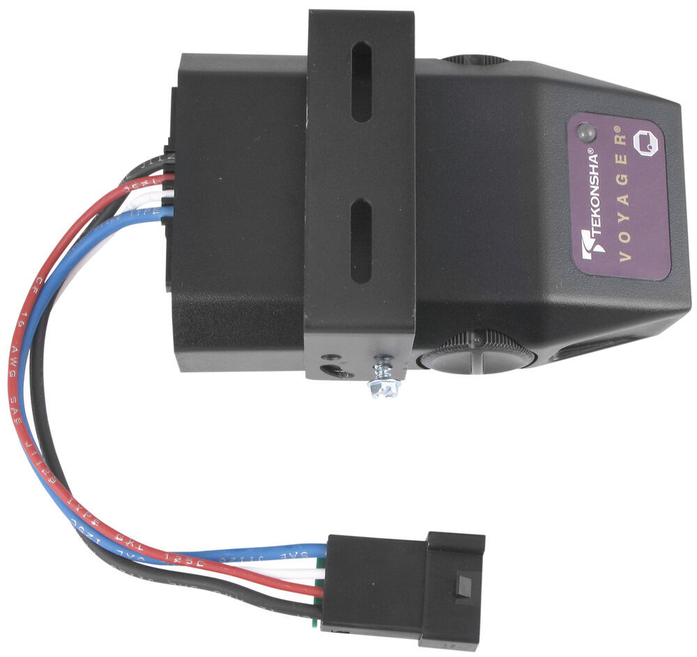
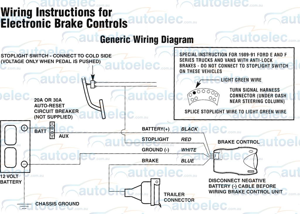
When it comes to installing or troubleshooting a Tekonsha Voyager Brake Controller, having access to a wiring diagram is crucial. A Tekonsha Voyager Brake Controller Wiring Diagram provides a visual representation of the electrical connections within the brake controller system, making it easier to understand and work with.
Why Tekonsha Voyager Brake Controller Wiring Diagrams are Essential
- Helps in proper installation of the brake controller
- Aids in troubleshooting electrical issues
- Ensures correct wiring connections for optimal performance
Reading and Interpreting Tekonsha Voyager Brake Controller Wiring Diagrams
When looking at a Tekonsha Voyager Brake Controller Wiring Diagram, it is important to understand the symbols and color codes used. Each wire is represented by a specific color, and each connection point is labeled for easy identification. Following the diagram step by step will ensure that the brake controller is installed correctly and functions as intended.
Using Tekonsha Voyager Brake Controller Wiring Diagram for Troubleshooting
If you are experiencing electrical problems with your Tekonsha Voyager Brake Controller, referring to the wiring diagram can help pinpoint the issue. By tracing the connections and checking for any loose wires or faulty connections, you can troubleshoot and resolve the problem effectively.
Importance of Safety
Working with electrical systems can be dangerous, so it is important to prioritize safety when using wiring diagrams. Here are some safety tips to keep in mind:
- Always disconnect the power source before working on the brake controller
- Use insulated tools to prevent electric shocks
- Double-check all connections before powering up the system
- If you are unsure about any aspect of the wiring diagram, seek professional help
Tekonsha Voyager Brake Controller Wiring Diagram
Tekonsha Voyager Brake Controller Wiring Diagram For Your Needs

Tekonsha Voyager Electric Brake Controller Wiring Diagram

Tekonsha Voyager Wiring Diagram / Troubleshooting Tekonsha Voyager

Tekonsha Voyager 9030 Wiring Diagram – Wiring Diagram Pictures

Tekonsha Voyager Xp Brake Controller Wiring Diagram – Wiring Flow Line

Tekonsha Brake Controller Wiring Diagram – True Story
