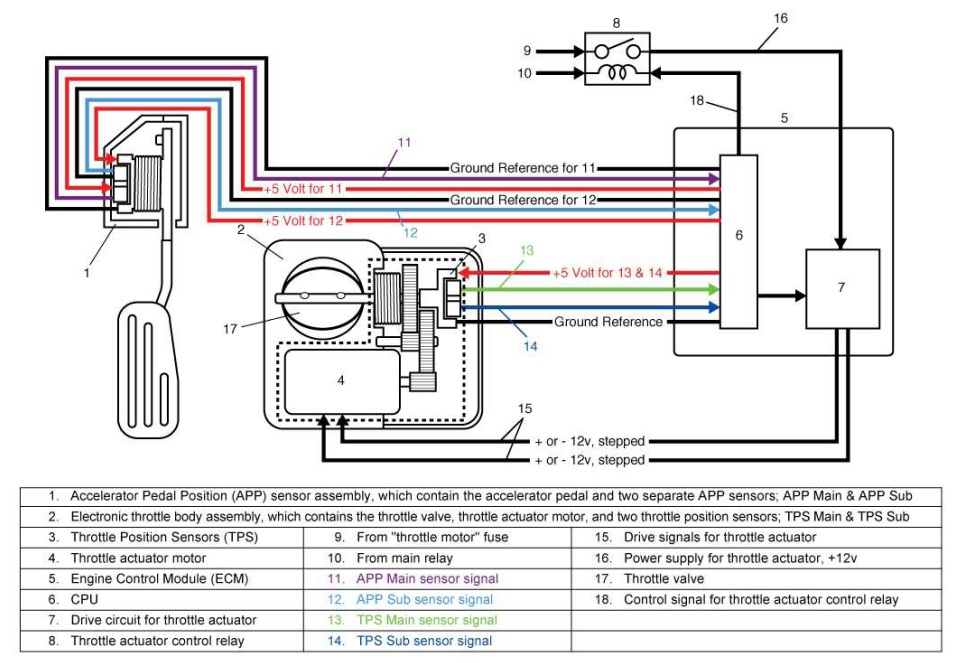
Toyota Throttle Position Sensor Wiring Diagram is a crucial tool for understanding the wiring of the throttle position sensor in Toyota vehicles. This diagram provides a detailed illustration of the connections and components involved in the sensor’s electrical system, helping mechanics and technicians diagnose and repair any issues that may arise.
Why Toyota Throttle Position Sensor Wiring Diagrams are Essential
The Toyota Throttle Position Sensor Wiring Diagram is essential for the following reasons:
- Helps in understanding the layout of the sensor’s wiring system
- Aids in diagnosing electrical problems related to the throttle position sensor
- Guides in the proper installation and repair of the sensor
How to Read and Interpret Toyota Throttle Position Sensor Wiring Diagrams
Reading and interpreting the Toyota Throttle Position Sensor Wiring Diagram effectively requires the following steps:
- Identify the components and connections in the diagram
- Understand the symbols and colors used in the diagram
- Follow the flow of the wiring from the sensor to other components
Using Toyota Throttle Position Sensor Wiring Diagrams for Troubleshooting
Toyota Throttle Position Sensor Wiring Diagrams can be used for troubleshooting electrical problems in the following ways:
- Locating and inspecting damaged or faulty wiring connections
- Testing the continuity of wires to ensure proper electrical flow
- Identifying potential short circuits or open circuits in the wiring system
Importance of Safety
When working with electrical systems and using wiring diagrams, it is crucial to prioritize safety. Here are some safety tips and best practices to follow:
- Always disconnect the vehicle’s battery before working on the electrical system
- Use insulated tools to prevent electrical shocks
- Avoid working on the electrical system in wet or damp conditions
- Refer to the vehicle’s service manual for specific safety precautions
Toyota Throttle Position Sensor Wiring Diagram
Toyota Throttle Position Sensor Wiring Diagram – Naturalfer

Toyota Throttle Position Sensor Wiring Diagram – Naturalfer

Toyota Throttle Position Sensor Wiring Diagram – Naturalfer

Toyota Throttle Position Sensor Wiring Diagram

Toyota throttle control

Throttle Position Sensor Wiring Diagrams & Color Codes | Toyota Q&A
