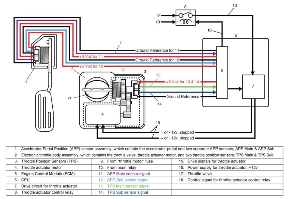
When it comes to working on vehicles, understanding the Tps Sensor Wiring Diagram is crucial for diagnosing and fixing electrical issues. The Tps Sensor Wiring Diagram provides a visual representation of the connections between the Throttle Position Sensor (TPS) and the vehicle’s electrical system. By studying this diagram, mechanics can pinpoint the source of a problem and make the necessary repairs.
Why Tps Sensor Wiring Diagrams are essential
Tps Sensor Wiring Diagrams are essential for several reasons:
- Help identify the wiring connections for the TPS sensor
- Aid in troubleshooting electrical problems related to the TPS sensor
- Guide mechanics in replacing or repairing faulty wiring
How to read and interpret Tps Sensor Wiring Diagrams effectively
Reading and interpreting Tps Sensor Wiring Diagrams can be overwhelming at first, but with practice, it becomes easier. Here are some tips to help you navigate through a Tps Sensor Wiring Diagram:
- Start by identifying the TPS sensor on the diagram
- Follow the lines to trace the connections between the TPS sensor and other components
- Pay close attention to the color codes and symbols used in the diagram
Using Tps Sensor Wiring Diagrams for troubleshooting electrical problems
Tps Sensor Wiring Diagrams are invaluable tools for troubleshooting electrical issues. By referring to the diagram, mechanics can:
- Determine if there are any loose or damaged connections
- Check for short circuits or open circuits
- Verify the voltage and ground connections to the TPS sensor
It’s important to remember that safety should always be a top priority when working with electrical systems. Here are some safety tips and best practices to keep in mind:
- Always disconnect the battery before working on any electrical components
- Use insulated tools to prevent electric shock
- Avoid working on electrical systems in wet or damp conditions
- Double-check your work before reassembling the components
Tps Sensor Wiring Diagram
P0122 Code: Throttle Position Sensor/Switch A Circuit Low Input – In

3, 4, 5, 6, & 8 Wire Throttle Position Sensor Wiring Diagram – TPS

Ford Tps Wiring Diagram

2008 F250 5.4 Throttle Position Sensor Wiring Diagram

Chevy Throttle Body Wiring Diagram – Wiring Diagram
Accelerator Pedal Position Sensor Wiring Diagram – inspirenetic
