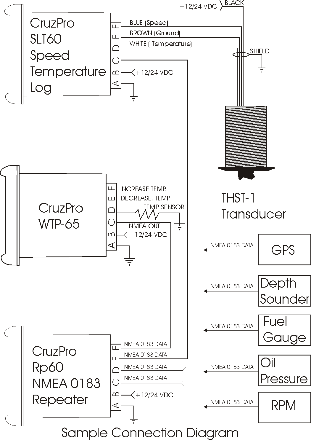
Are you looking to understand more about Vdo Rev Counter Wiring Diagram? These diagrams are essential tools for mechanics and DIY enthusiasts alike, providing a clear and detailed overview of the wiring connections for a Vdo rev counter. By following these diagrams, you can ensure proper installation and troubleshooting of your rev counter.
Why are Vdo Rev Counter Wiring Diagrams Essential?
- Ensure correct installation of the rev counter
- Help troubleshoot any wiring issues
- Provide a clear visual representation of the wiring connections
How to Read and Interpret Vdo Rev Counter Wiring Diagrams
When looking at a Vdo Rev Counter Wiring Diagram, it’s important to understand the symbols and colors used to represent different components and connections. Here are some key tips:
- Refer to the legend or key provided on the diagram for guidance
- Follow the lines and arrows to trace the connections between components
- Pay attention to the color-coding of wires for proper identification
Using Vdo Rev Counter Wiring Diagrams for Troubleshooting
When faced with electrical problems related to your Vdo rev counter, the wiring diagram can be a valuable tool for troubleshooting. By following the diagram and checking the connections, you can identify and resolve issues such as faulty wiring, loose connections, or damaged components.
Importance of Safety
Working with electrical systems can be dangerous, so it’s crucial to prioritize safety when using wiring diagrams. Here are some safety tips to keep in mind:
- Always disconnect the power source before working on any electrical components
- Use insulated tools to prevent electric shock
- Avoid working on electrical systems in wet or damp conditions
- Double-check all connections before restoring power to the circuit
Vdo Rev Counter Wiring Diagram
Vdo Rev Counter Wiring Diagram

Vdo Rev Counter Wiring Diagram

Vdo Rev Counter Wiring Diagram

Vdo rev counter | The Late Bay

Vdo Senders Wiring Diagrams

Electrics – VDO Rev Counter Wiring | Volkszone Forum
