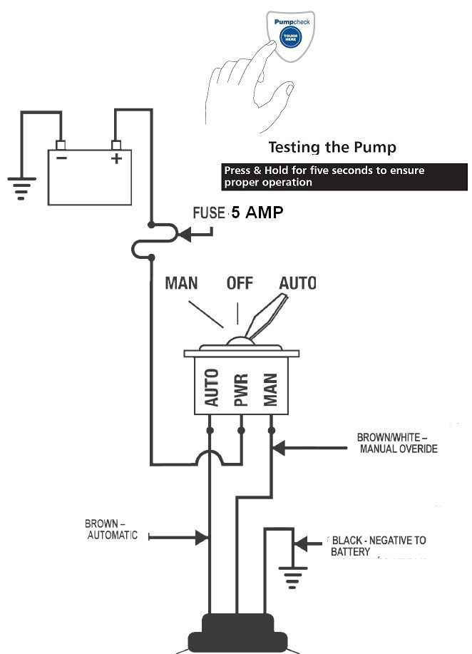
When it comes to ensuring the proper functioning of your boat’s bilge pump system, understanding the Rule Bilge Pump Switch Wiring Diagram is crucial. This diagram provides a visual representation of how the various components of the bilge pump system are connected and how electricity flows through them.
Why Rule Bilge Pump Switch Wiring Diagrams are Essential
- Helps in understanding the electrical connections of the bilge pump system.
- Aids in troubleshooting electrical issues efficiently.
- Ensures proper installation and maintenance of the bilge pump system.
Reading and Interpreting Rule Bilge Pump Switch Wiring Diagrams
When looking at a Rule Bilge Pump Switch Wiring Diagram, it’s essential to understand the symbols and colors used to represent different components and connections. Here are some key points to keep in mind:
- Follow the flow of electricity from the power source to the pump.
- Identify the various switches, fuses, and connections in the diagram.
- Pay attention to the color-coding of wires for easy identification.
Using Rule Bilge Pump Switch Wiring Diagrams for Troubleshooting
Rule Bilge Pump Switch Wiring Diagrams are invaluable when it comes to diagnosing and fixing electrical problems in your boat’s bilge pump system. Here’s how you can use them effectively:
- Trace the path of electricity to identify any breaks or loose connections.
- Check the switches and fuses to ensure they are functioning properly.
- Refer to the wiring diagram to determine the correct sequence of connections.
Importance of Safety
Working with electrical systems can be dangerous, so it’s crucial to prioritize safety when using Rule Bilge Pump Switch Wiring Diagrams. Here are some safety tips to keep in mind:
- Always disconnect the power source before working on the electrical system.
- Use insulated tools to avoid electrical shocks.
- Double-check your work to ensure all connections are secure and correct.
Rule Bilge Pump Switch Wiring Diagram
Rule 1100 Automatic Bilge Pump Wiring Diagram For Your Needs

Rule Mate Bilge Pump Wiring

Rule Bilge Pump Wireing

The Step-by-Step Guide to Wiring a Bilge Pump: Ensure Smooth Sailing

Bilge Pump Switch Wiring Diagram
